
Our machine aims to green the city’s facades.
It is accessible for all and does not require daily maintenance.
You just have to hang it on your balcony with a light sensor that will define the amount of sun exposure needed for the plant.
Thanks to a motor, the plant will be more or less protected all year long depending on the season.
Moreover, a hydroponic water system will supply the green wall with water permanently.
This machine is a gesture towards our future green city
Construction steps in video !
(soundOn)
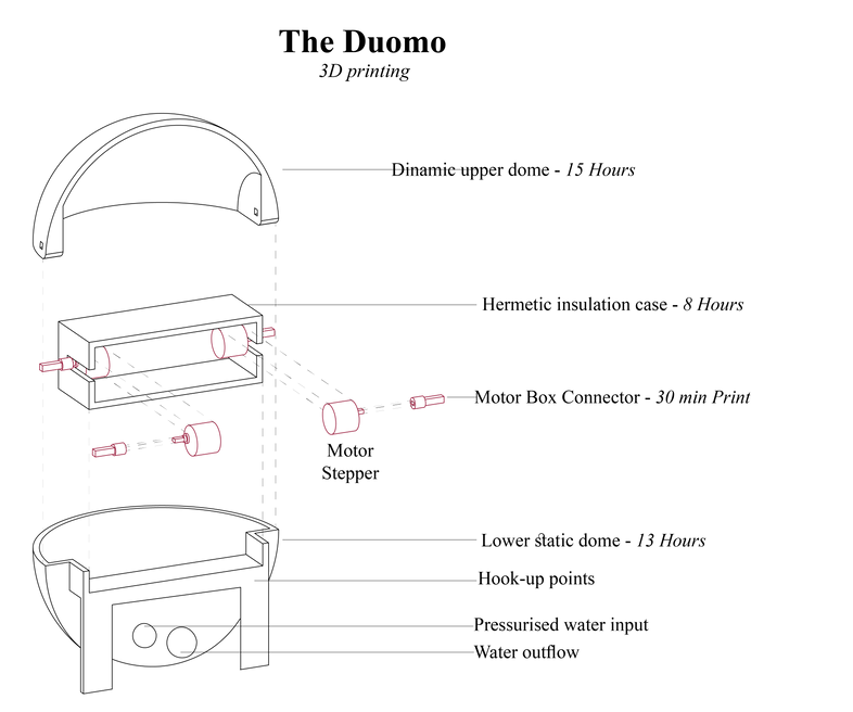


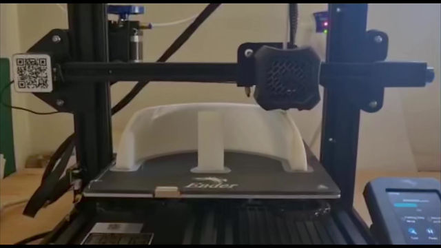
We decided to 3D print our machine so that it would be rigid and waterproof.
We looked for a system that would allow us to concentrate the electronics and the water system in one place.
The printing of the machine took 36 hours. Due to the time we decided to split the printing on two machines, which created these different colours.
size: 20/10cm
Material: P.A.L
Bed heat: 50°C
Material heat: 200°C

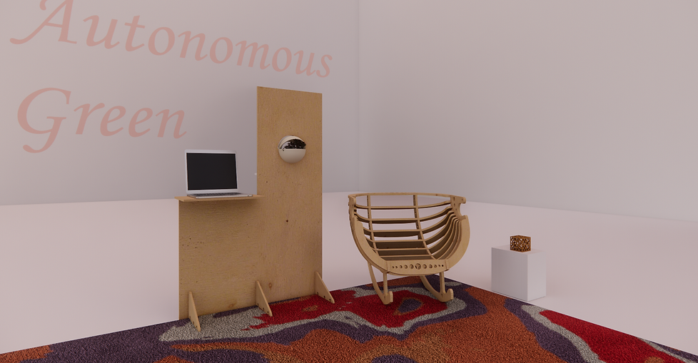
We have created a wooden stand to support our machine .
We are aware that wood is not suitable for this machine. If we had been able to further develop and improve our project we would have used white recycled plastic.


We then connected the dome to Arduino to allow the upper dome to open or close with different degrees of stop depending on the intensity of the sun.
The objective of this code is to identify the needs of the plant in order to determine the rate of light needed for its photosynthesis per 24H cycle.
In the beginning, the code starts by identifying the stepper, variables, and sensors.
Then, the code initializes the serial port.
After that, the code starts with the if statements. The code asks the stepper to rotate in a certain direction at a certain speed depending on the value the light sensor measures.
So basically, the stepper closes if there is no light and opens depending on the light intensity.
CODE
#include <Stepper.h>
// change this to fit the number of steps per revolution
// for your motor
int stepsPerRevolution=32;
const int sensorpin = 0;
int execute=0;
int execute1=0;
int execute2=0;
int execute3=0;
int execute4=0;
int lightcal;
Stepper myStepper(stepsPerRevolution, 8, 10, 9, 11);
// initialize the stepper library pins:
void setup() {
// initialize the serial port:
Serial.begin(9600);
}
void loop() {
// step one revolution in one direction:
lightcal = analogRead(sensorpin);
delay(500);
Serial.println(lightcal);
if(lightcal <250 && lightcal>100 && execute==0){
stepsPerRevolution = 150;
//Stepper myStepper(stepsPerRevolution, 8, 9, 10, 11);
myStepper.setSpeed(100);
myStepper.step(stepsPerRevolution);
Serial.println("clockwise");
execute++;
}
if(lightcal<500 && lightcal>250 && execute1==0){
stepsPerRevolution = 150;
myStepper.setSpeed(100);
myStepper.step(stepsPerRevolution);
Serial.println("clockwise");
execute1++;
}
if(lightcal<750 && lightcal>500 && execute2==0){
stepsPerRevolution = 150;
myStepper.setSpeed(100);
myStepper.step(stepsPerRevolution);
Serial.println("clockwise");
execute2++;
}
if(lightcal<1023 && lightcal>750 && execute3==0){
stepsPerRevolution = 150;
myStepper.setSpeed(100);
myStepper.step(stepsPerRevolution);
Serial.println("clockwise");
execute3++;
}
if(lightcal<100 ){
Serial.println("counterclockwise");
int steps=450;
myStepper.step(-steps);
delay(500);
}
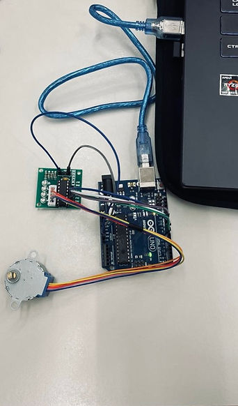
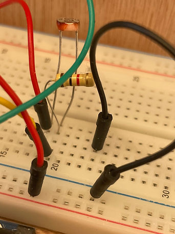
Light sensor and Resistor .


- The two motors screwed-
allowing movment and to fix the top and bottom parts


Since we used two steppers and two photoresistors, we used two Arduinos to connect everything.
The cables were not long enough to be connected to the same motherboard. Another reason is that the Arduino gives only 5 volts. We did not have enough knowledge to connect everything on the same motherboard.
we also CNC cut the wooden support on which we added two tables, 9cm apart, knowing that the cable was 20cm long.
The large table for the computer and the small one for the electronics.
Step 1 - Defining sensors, Stefar, and variables
Step 2 - The Loop with All Legal States (IF)
-At this point there is 1-light 250-500 spinning spinning at 45 degrees
- light 500-750 stifs rotating another 45 degrees (reaches 90 degrees)
- light 750-1000 stifs rotating another 45 degrees (reaches 135 degrees)
- Signal under 250 stifter spinning towards 135 degrees
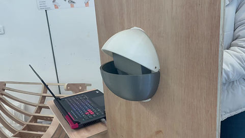

Playing with light intensity
The different degrees of stops
After checking that the electronics were working properly we activated the aerophonic system.
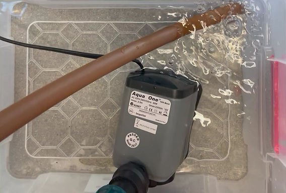

The water is in a closed system that allows for economy and better water management.
It is powered by a 45 Watt electric pump with a 20 mm outlet connected to 16 mm pipes.

We have added a drainage control handle to manage the quantity of water drained in order to control the intensity of the drainage in relation to the quantity of water


In an aeroponic system, the plants are placed on foam discs which keep the moisture in, repel insects and keep them in place. The roots are completely exposed under this foam and are suspended from small misting systems.
This foam allowed us to block any splashes, especially towards the electronic area


